-
-
Core manufacturer数字Our AdvantageApplicationOur honor certificate
-
Case classification
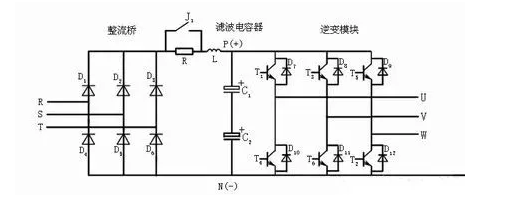
Frequency inverter phase fault is one of the common faults, to know that frequency inverter products are mainly single-phase 220V and three-phase 380V distinction, of course, the input phase detection only exists in three-phase products. Figure 1 shows the main circuit of the frequency inverter, R, S, T are three-phase AC inputs, when one of the phases is disconnected because of the fault of the fuse or circuit breaker, it is considered that the input phase fault has occurred.

In addition to the input phase fault, there is also an output phase fault, which will directly cause the motor to run without phase. When the phase is missing, the motor starts when it is stationary, and the motor cannot turn. If the lack of phase in operation is very dangerous, the motor current increases 1.2 times, the heat is serious, the vibration is aggravated, and the motor is easily burned. By detecting the output current, the frequency inverter can determine whether the three-phase output is out of phase.
Detection method of frequency inverter input phase deficiency
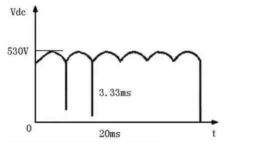
When the frequency converter does not operate under normal conditions without phase loss, the voltage on Udc is shown in Figure 2. There will be 6 wave heads in one power frequency cycle, and the DC voltage Udc will not be lower than 470V. In fact, for a 7.5kW frequency converter, the value of C is generally 900uf. It can be calculated that the periodic voltage drop is roughly 40V, and the ripple coefficient will not exceed 7.5%. When the input phase loss occurs, there are only two voltage wave heads in one power frequency cycle, and the minimum value of the rectifier voltage is zero. At this time, under the above conditions, it can be estimated that the voltage drop is roughly 150V, and the ripple coefficient should reach about 30%.

It can be seen that when the frequency inverter is still running after the input phase is missing, the capacitor C will be repeatedly charged in a wide range, which is not allowed, and it will inevitably cause damage to the capacitor, resulting in damage to the entire frequency inverter. Moreover, if the load is light, although it will not cause damage to the capacitor, the ripple coefficient of the DC voltage will increase a lot compared with normal times, and the current frequency converter generally has a constant voltage control function, which will cause the oscillation of the switching duty ratio and the oscillation of the load current. When the load is heavy, the rectifier bridge is further damaged, and the frequency converter failure probability is increased, such as phase deficiency occurs when the power is transmitted, and the frequency converter is easily burned due to single-phase high-current operation.
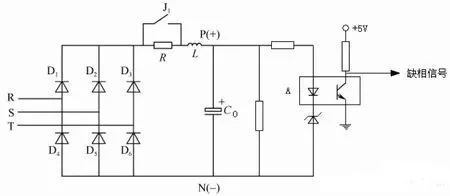
One of the simplest ways to detect frequency inverter input phase deficiency is to use hardware detection, as shown in Figure 3. The voltage level on C0 in the circuit will reflect that R, S, T three-phase input has A missing phase, when the phase loss occurs, the voltage on C0 will be reduced, the optical lotus device will not be switched on, and the signal at point A is high, corresponding to the occurrence of phase loss.

Hardware detection method of frequency inverter input phase deficiency
Of course, the input phase loss detection can also be carried out from the software. This is because under normal circumstances, the period of the main AC component of the Udc, except for the DC component, is 3.33ms. However, in the case of phase loss, the period of the main AC component will become 10ms. Therefore, by detecting the period of the AC component of the Udc, it can be determined whether it is phase lost.
The countermeasures of frequency inverter phase fault
When the frequency converter has a phase failure, it can be checked from the following aspects:
First of all, the input and output of the frequency inverter are judged by the voltmeter or clamp meter.
(1) Check whether the input and output lines of the frequency inverter are normal.
Many of the faults of the frequency inverter are from the peripheral lines, such as circuit breakers, contactors, reactors, filters, etc., only to ensure that the peripheral lines are correct, in order to make the frequency inverter work in a safe and reliable electrical environment.
(2) Check the main circuit inside the frequency inverter, including the rectifier bridge, IGBT and drive board.

Please fill out the form below to request a quote or to request more information about us. please be as detailed as possible in your message, and we will get back to you as soon as possible with a response. we're ready to start working on your new project